C14 Power Inlet, Screw Mount, Schurter 6100-3
The Schurter 6100-3 power inlet (IEC 60320 power inlet): flange width 48 mm, flange height 23 mm, front face width 28 mm. Available as simplified STEP files.
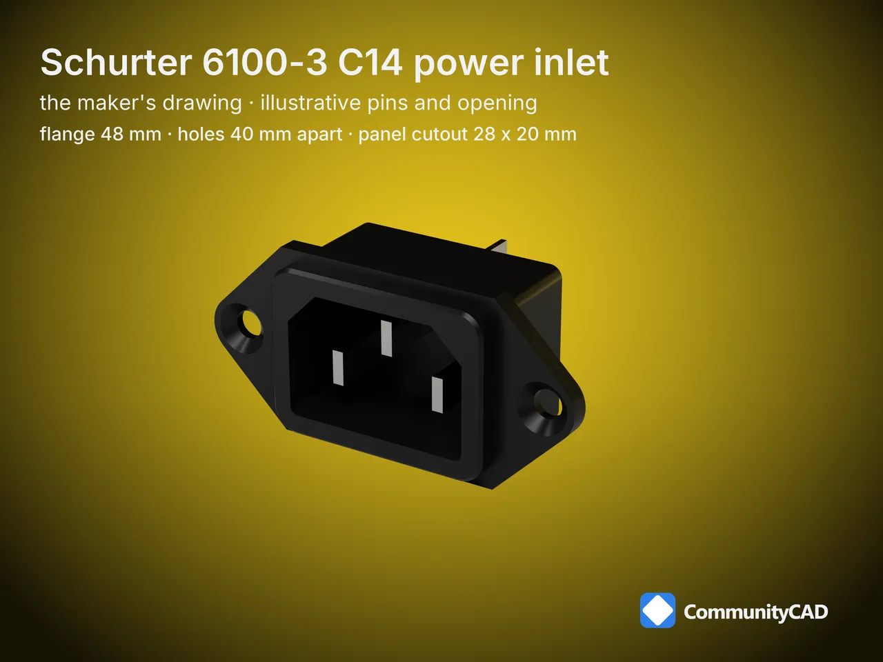
This model is CommunityCAD's own, drawn from SCHURTER's published drawing; SCHURTER did not make or endorse it.
How these parts are made, and what the levels mean: read the method
- Also known as: Schurter 6100-3 IEC inlet, Schurter 6100-3 IEC power socket, Schurter 6100-3 mains inlet, Schurter 6100-3 power entry module, Schurter 6100-3 panel mount power connector
- Model id:
iec-inlets-schurter-6100-3
- Standard: IEC 60320 power inlet · size Schurter 6100-3
Files
| Part key | Simplified |
|---|
iec-inlets-schurter-6100-3 | STEP |
Dimensions
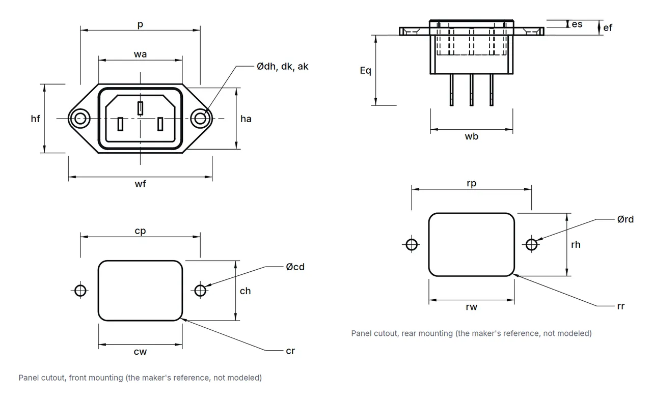
| Symbol | Name | min | nom | max | Modeled | Rule | Level |
|---|
| wf | Flange width | | 48 | | 48 | nominal | L2 |
| hf | Flange height | | 23 | | 23 | nominal | L2 |
| wa | Front face width | | 28 | | 28 | nominal | L2 |
| ha | Front face height | | 20.5 | | 20.5 | nominal | L2 |
| ef | Front height | | 5 | | 5 | nominal | L2 |
| es | Front face projection | | 2.5 | | 2.5 | nominal | L2 |
| p | Mounting hole pitch | | 40 | | 40 | nominal | L2 |
| dh | Mounting hole diameter | | 3.5 | | 3.5 | nominal | L2 |
| dk | Countersink diameter | | 6.3 | | 6.3 | nominal | L2 |
| ak | Countersink angle | | 90 | | 90 | nominal | L2 |
| wb | Body width | | 27.5 | | 27.5 | nominal | L2 |
| hb | Body height | | 19.5 | | 19.5 | nominal | L2 |
| Es | Terminal length, solder | | 20.5 | | 20.5 | nominal | L2 |
| Eq | Terminal length, quick connect | | 23.5 | | 23.5 | nominal | L2 |
| cw | Cutout width | | 28 | | 28 | nominal | L2 |
| ch | Cutout height | | 20 | | 20 | nominal | L2 |
| cr | Cutout corner radius | | | 3 | 3 | single limit (max), modeled at the limit | L2 |
| cp | Cutout hole pitch | | 40 | | 40 | nominal | L2 |
| cd | Cutout hole diameter | | 3.5 | | 3.5 | nominal | L2 |
| cm | Cutout hole thread | | 3 | | 3 | nominal | L2 |
| rw | Rear-mounting cutout width | | 28.5 | | 28.5 | nominal | L2 |
| rh | Rear-mounting cutout height | | 21 | | 21 | nominal | L2 |
| rr | Rear-mounting cutout corner radius | | | 3 | 3 | single limit (max), modeled at the limit | L2 |
| rp | Rear-mounting hole pitch | | 40 | | 40 | nominal | L2 |
| rd | Rear-mounting hole diameter | | 3.5 | | 3.5 | nominal | L2 |
| rm | Rear-mounting hole thread | | 3 | | 3 | nominal | L2 |
| smax | Panel thickness, greatest | | | 8 | 8 | single limit (max), modeled at the limit | L2 |
Drawing
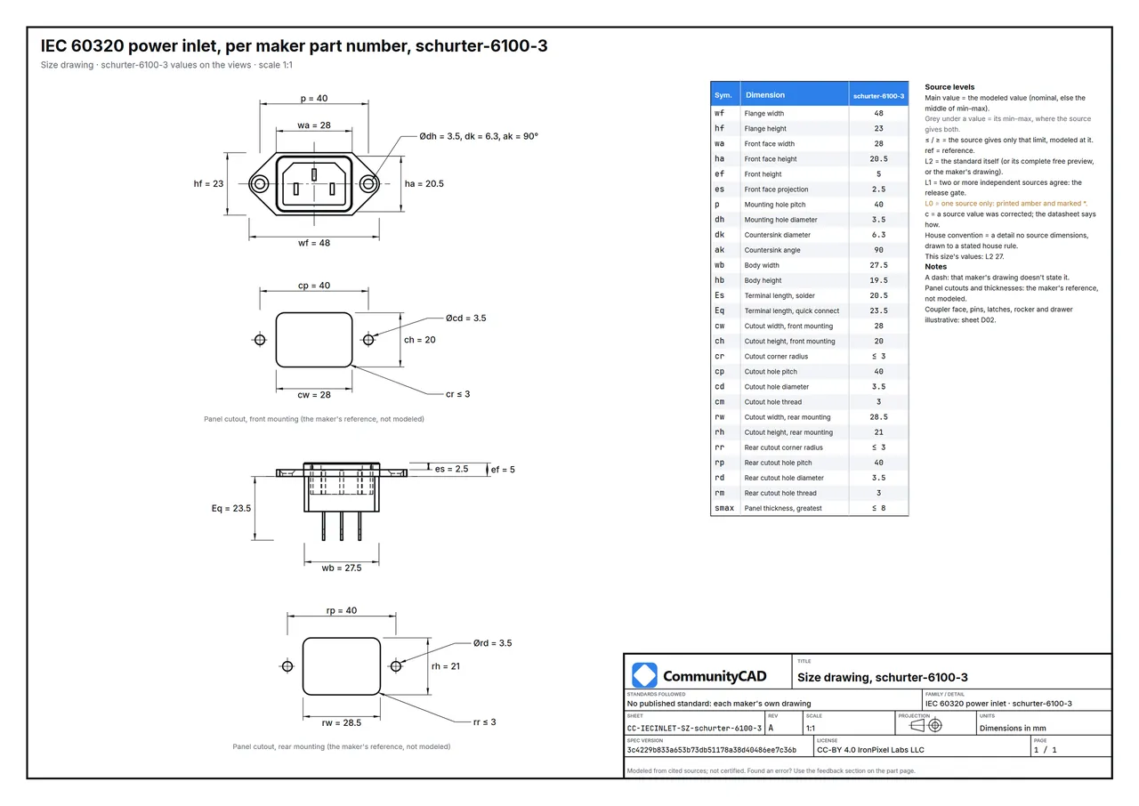
As a PDF: CC-IECINLET-SZ-schurter-6100-3.pdf.
The Schurter 6100-3 power inlet beside the Qualtek 703W-00/08
The Schurter 6100-3 is the first of the 5 IEC 60320 power inlets published here, listed from Schurter 6100-3 to Schurter 2573.
- Flange width (wf): 48 mm on the Schurter 6100-3 power inlet, against 49.5 mm on the Qualtek 703W-00/08.
- Front face width (wa): 28 mm on the Schurter 6100-3 power inlet, against 30 mm on the Qualtek 703W-00/08.
- Front face height (ha): 20.5 mm on the Schurter 6100-3 power inlet, against 22 mm on the Qualtek 703W-00/08.
- Front height (ef): 5 mm on the Schurter 6100-3 power inlet, against 6 mm on the Qualtek 703W-00/08.
- Mounting hole pitch (p): 40 mm on the Schurter 6100-3 power inlet, the same on the Qualtek 703W-00/08.
- Mounting hole diameter (dh): 3.5 mm on the Schurter 6100-3 power inlet, against 3.4 mm on the Qualtek 703W-00/08.
Other sizes
Conventions
- Simplified only: the moulded body and its metal contacts as separate solids. STEP AP214, millimetres, the flange's back face at z = 0, the front face toward +Z.
- The panel cutout and panel thickness are the maker's own, given as reference data on the page and drawing; they are not modeled.
Documents
Sources
schurter-6100-3. Full citations: the method page and this size's datasheet.
Found an error? Use the feedback section on this page.







Comments
Sign in to leave a comment.
Loading comments...