20 B-type slot 6 double Extrusion Corner Bracket
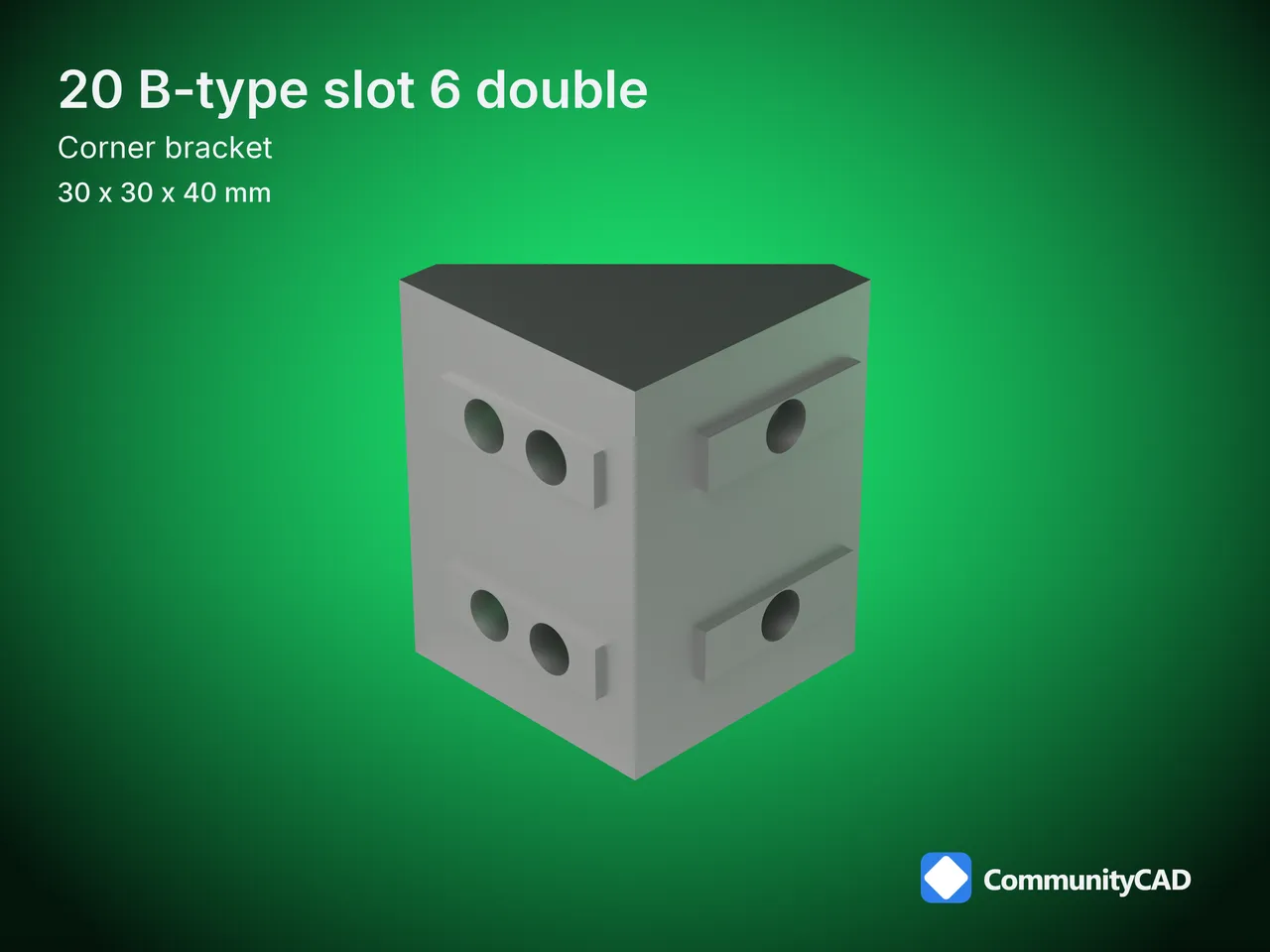
Legs of 30 mm and 30 mm, 40 mm across, with 5.2 mm holes: the 20 B-type slot 6 double extrusion corner bracket, as simplified STEP files.

How these parts are made, and what the levels mean: read the method
- Also known as: 20 B-type slot 6 double cast angle bracket, 20 B-type slot 6 double angle corner connector, 20 B-type slot 6 double L bracket, 20 B-type slot 6 double gusset bracket
- Model id:
extrusion-corner-brackets-b6-double
- Standard: Extrusion corner bracket · size 20 B-type slot 6 double
Files
| Part key | Simplified |
|---|
extrusion-corner-brackets-b6-double | STEP |
Dimensions

| Symbol | Name | min | nom | max | Modeled | Rule | Level |
|---|
| l | Leg length | | 30 | | 30 | nominal | L0 (nom: one source) |
| h | Upright leg length | | 30 | | 30 | nominal | L0 (nom: one source) |
| w | Width | | 40 | | 40 | nominal | L0 (nom: one source) |
| t | Wall thickness | | 4.5 | | 4.5 | nominal | L0 (nom: one source) |
| d | Hole diameter | | 5.2 | | 5.2 | nominal | L0 (nom: one source) |
| n | Number of holes | | 6 | | 6 | nominal | L0 (nom: one source) |
| k | Key height | | 1 | | 1 | nominal | L0 (nom: one source) |
| ex | Hole row on the first leg | | 10 | | 10 | nominal | L0 (nom: one source) |
| ex2 | Second hole row on the first leg | | 18 | | 18 | nominal | L0 (nom: one source) |
| ez | Hole row on the upright leg | | 18 | | 18 | nominal | L0 (nom: one source) |
| ey | Hole column from the side | | 10 | | 10 | nominal | L0 (nom: one source) |
| py | Hole column spacing | | 20 | | 20 | nominal | L0 (nom: one source) |
Drawing

As a PDF: CC-CORNBRKT-SZ-b6-double.pdf.
The 20 B-type slot 6 double extrusion corner bracket beside the 20 B-type slot 6 single and the 20 V-slot single
The 20 B-type slot 6 double is number 2 of the 10 Extrusion corner brackets published here, listed from 20 B-type slot 6 single to 45 slot 10 single.
- Leg length (l): 30 mm on the 20 B-type slot 6 double extrusion corner bracket, against 30 mm on the 20 B-type slot 6 single and 20 mm on the 20 V-slot single.
- Upright leg length (h): 30 mm on the 20 B-type slot 6 double extrusion corner bracket, against 30 mm on the 20 B-type slot 6 single and 20 mm on the 20 V-slot single.
- Width (w): 40 mm on the 20 B-type slot 6 double extrusion corner bracket, against 20 mm on the 20 B-type slot 6 single and 20 mm on the 20 V-slot single.
- Wall thickness (t): 4.5 mm on the 20 B-type slot 6 double extrusion corner bracket, the same on the 20 B-type slot 6 single.
- Hole diameter (d): 5.2 mm on the 20 B-type slot 6 double extrusion corner bracket, against 5.3 mm on the 20 B-type slot 6 single and 7.2 mm on the 20 V-slot single.
- Number of holes (n): 6 on the 20 B-type slot 6 double extrusion corner bracket, against 3 on the 20 B-type slot 6 single.
- Key height (k): 1 mm on the 20 B-type slot 6 double extrusion corner bracket, the same on the 20 B-type slot 6 single.
- Hole row on the first leg (ex): 10 mm on the 20 B-type slot 6 double extrusion corner bracket, the same on the 20 B-type slot 6 single.
Other sizes
Conventions
- Simplified only: one solid. STEP AP214, millimetres, the corner where the legs' profile faces meet on the Y axis, one leg's face at Z = 0 along +X, the other's at X = 0 up +Z, the width across Y from 0.
- Side walls, rib, key width and length, inside fillet and the curved diagonal are illustrative, not any maker's design.
- The CommunityCAD mark recessed 0.3 mm in an outside side wall, illustrative.
Documents
Sources
misumi-cast-brackets. Full citations: the method page and this size's datasheet.
Found an error? Use the feedback section on this page.

Comments
Sign in to leave a comment.
Loading comments...