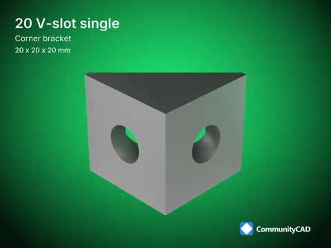
Extrusion corner bracket, per profile system, vs-single
Size drawing - vs-single values on the views - enlarged 5:1
Sym. | Dimensi vs-single
* L Leg length 20
x Upright leg length ai)
20*
~50* Counterbore floor Soe
.20* Hole diameter 7.20
11* Counterbore diameter
* Toe flat 1
Source levels
Main value = the modeled value (nominal, else the middle of min-max).
Li Grey under a value = its min-max, where the source gives both.
@dc = 11* < / = = the source gives only that limit, modeled at it. ref = reference.
L2 = the standard itself (or its complete free preview, or the maker's drawing).
L1 = two or more independent sources agree: the release gate.
LO = one source only: printed amber and marked *.
c = a source value was corrected; the datasheet says how.
House convention = a detail no source dimensions, drawn to a stated house rule. This size's values: LO 7.
Notes
No published standard: each value the reference maker's drawing, single source (ADR 0034). Side walls, keys' width and length, fillet and mark are illustrative: sheet DO2.
TITLE
'? CommunityCAD Size drawing, vs-single
STANDARDS FOLLOWED FAMILY / DETAIL No published standard (makers' drawings) Extrusion corner bracket - vs-single
SHEET REV SCALE PROJECTION UNITS
CC-CORNBRKT-SZ-vs-single |A 5:1 & Dimensions in mm SPEC VERSION LICENSE PAGE 304229b833a653b73db51178a38d40486ee7c36b CC-BY 4.0 IronPixel Labs LLC 1/1
Modeled from cited sources; not certified. Found an error? Use the feedback section on the part page.