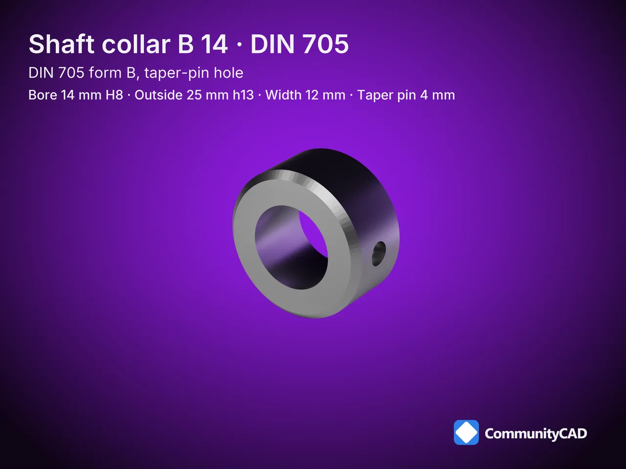
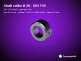
The 14 mm shaft collar (DIN 705, form B, taper-pin hole) locks onto a 14 mm shaft with a 4 mm hole for a taper pin, reamed with the shaft; it is 25 mm across and 12 mm wide. Get it as simplified STEP files.

How these parts are made, and what the levels mean: read the method
- Also known as: 14 mm set collar, 14 mm adjusting ring, 14 mm stop collar, 14 mm Stellring
- Model id:
din705-b-d14
- Standard: DIN 705:2019 · size 14 mm
Files
| Part key | Simplified |
|---|
din705-b-d14 | STEP |
Dimensions

| Symbol | Name | min | nom | max | Modeled | Rule | Level |
|---|
| d1 | Bore diameter | | 14 | | 14 | nominal | L1 |
| d2 | Outside diameter | | 25 | | 25 | nominal | L1 |
| b | Width | | 12 | | 12 | nominal | L1 |
| d4 | Taper-pin diameter | | 4 | | 4 | nominal | L1 |
Drawing

As a PDF: CC-DIN705-SZ-14.pdf.
The 14 mm is number 7, counting from the smallest, of the 10 DIN 705 shaft collars published here, from 4 mm to 20 mm.
- Bore diameter (d1): 14 mm on the 14 mm form B shaft collar, against 12 mm on the 12 mm and 16 mm on the 16 mm.
- Outside diameter (d2): 25 mm on the 14 mm form B shaft collar, against 22 mm on the 12 mm and 28 mm on the 16 mm.
- Width (b): 12 mm on the 14 mm form B shaft collar, the same on the 12 mm and the 16 mm.
- Taper-pin diameter (d4): 4 mm on the 14 mm form B shaft collar, the same on the 12 mm and the 16 mm.
Other sizes
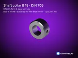
- One size smaller: 12 mm Shaft Collar, DIN 705, Form B (Taper-pin Hole), 12 mm bore, 22 mm OD, 12 mm wide, 4 mm pin hole.
- One size larger: 16 mm Shaft Collar, DIN 705, Form B (Taper-pin Hole), 16 mm bore, 28 mm OD, 12 mm wide, 4 mm pin hole.
Conventions
- Form A: simplified and threaded; form B has no thread, simplified only. STEP AP214, millimetres, Z along the bore axis, the plain face at Z = 0 and the chamfered face at Z = b, the hole on +X at Z = b/2.
- d1 at the midpoint of its H8 band and d2 at the midpoint of its h13 band, from the ISO 286-2 grade widths; b, d3 and d4 at their nominals.
- Form A, threaded level: ISO 68-1 basic internal thread in the hole, right hand, coarse pitch, over the full wall.
Documents
Sources
dinmark-din705, dinmark-din705-b, fasten-it-din705, fasten-it-din705-b, maedler-din705. Full citations: the method page and this size's datasheet.
Found an error? Use the feedback section on this page.

Comments
Sign in to leave a comment.
Loading comments...