CC-IECINLET-DS-qualtek-703w-00-08 rev A Size datasheet - qualtek-703w-00-08
'?) CommunityCAD
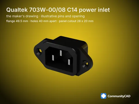
Qualtek 703W-00/08 C14 power inlet
Size datasheet: this size's values with their levels, conventions and sources.
— — For panel mounting: takes a C13 0 cord © © i Part key iec-inlets-qualtek-703w-00-08 Files 1 STEP AP214 (simplified)
qualtek-703w-00-08, front, 0.75:1 qualtek-703w-00-08, side, 0.75:1 (hidden lines dashed)
Sym. Dimension wt Flange width tf Flange thickness PL Flange lobe radius wa Front face width ha Front face height ra Front face corner radius wre Coupler opening width hr Coupler opening height ef Front height p Mounting hole pitch dh Mounting hole diameter dk Countersink diameter wb Body width hb Body height rb Body corner radius Lb Body depth Lt Terminal block depth tt Terminal thickness
Modeled value: nominal, else the midpoint of min-max. < / =: only that limit is given. * amber: one source (LO). c: a source value was corrected. Level - independent sources.
No published standard: each maker's own drawing Page 1/2 IEC 60320 power inlet - qualtek-703w-00-08 - Dimensions in mm - CC-BY 4.0, lronPixel Labs LLC spec 304229b833a653b73db51178a38d40486ee7c36b
Modeled from cited sources; not certified. Found an error? Use the feedback section on the part page.
---
CC-IECINLET-DS-qualtek-703w-00-08 rev A Size datasheet - qualtek-703w-00-08
'?) CommunityCAD
Dimensions (continued)
Sym. Dimension
cw Cutout width, front mounting ch Cutout height, front mounting er Cutout corner radius
cc Cutout chamfer (top corners) cp Cutout hole pitch
cd Cutout hole diameter
rw Cutout width, rear mounting rh Cutout height, rear mounting er Rear cutout corner radius
rp Rear cutout hole pitch
rd Rear cutout hole diameter
Conventions
« Each part its maker's drawing: No published standard for the body, flange, holes or panel cutout: every value is that part's maker drawing (L2, one lineage), CommunityCAD's model of it, not a Schurter or Qualtek file. IEC 60320-3 fixes only the coupler face and is paid.
« Panel cutouts are reference data: The panel cutout (front mounting, and rear mounting where the maker draws one) and panel thickness are the maker's own, on this page as reference; they are not modeled and aren't a shared "C14 cutout".
« Frame: The flange's back face (the panel's front face) at z = 0, the front face toward +Z, the body toward -Z, the mounting holes on X; the C14's earth pin toward +Y (DD11: toward +X, as Schurter draws it).
« Coupler opening and pins: Illustrative: the coupler opening's shape and depth and its pins (Qualtek's opening size where given), the flange outline between the drawn extents, the body's depth where only E is given, DD11's countersink diameter, rocker and fuse drawer, 6100-4's latches, the corner rounds and the terminal tabs.
« Terminals: Schurter's quick-connect variant (Eq) is modeled; its solder variant (Es) is recorded. Qualtek's solder pins as its drawing shows them.
Sources
Source Publisher Retrieved sha256
qualtek-703w-00-08 Qualtek Electronics Corp. 2026-11-08 c65de4540625 (kept outside the repo) qualtek-703w-00-08-figures Qualtek Electronics Corp. 2026-11-08 c65de4540625 (kept outside the repo)
The whole series (verification map, corrections, drawings): CC-IECINLET-DS.
No published standard: each maker's own drawing Page 2/2 IEC 60320 power inlet - qualtek-703w-00-08 - Dimensions in mm - CC-BY 4.0, lronPixel Labs LLC spec 304229b833a653b73db51178a38d40486ee7c36b
Modeled from cited sources; not certified. Found an error? Use the feedback section on the part page.