Hexapod

Hexapod
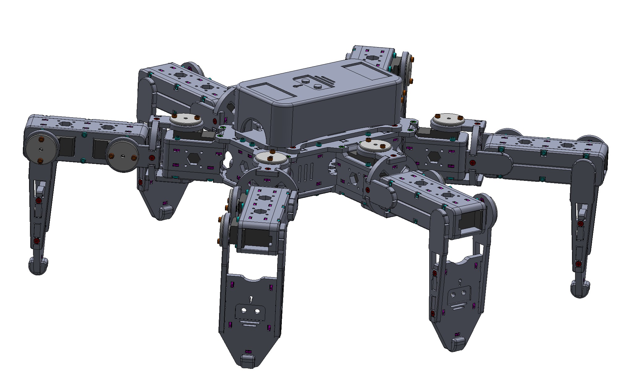
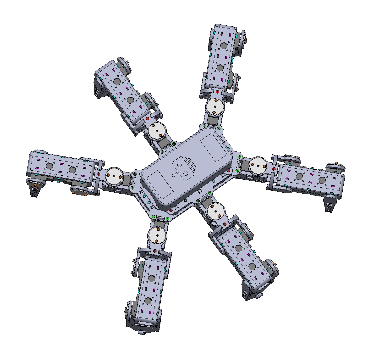
A 3D Printed Hexapod Robot
Overview
<img src="./images/hexapod-logo.svg" alt="logo" width="64"/> Hexapod
A 3D Printed Hexapod Robot
It is strongly recommended to start with Hexapod v2 rather than building Hexapod v1. Our experience has shown that MG90S servos used in Hexapod v1 frequently fail due to their inherent weaknesses and inconsistencies in quality.
<img src="./images/hexapod_photo.jpg" alt="hexapod_photo" width="300"/><img src="./images/hexapod_photo_battery.jpg" alt="hexapod_photo" width="300"/>
<img src="./images/hexapod_lego_1.jpg" alt="hexapod_photo" width="300"/><img src="./images/hexapod_lego_2.jpg" alt="hexapod_photo" width="300"/>
Introduction
This agile, 3D-printed hexapod robot is designed to work with either a Raspberry Pi PICO or an ESP32, providing flexibility and enhanced performance. Equipped with stronger and faster 21G servos, it offers a range of advanced features, including:
- A robust, durable structure
- WiFi-enabled remote control
- Smooth, agile movement
- Over-the-air (OTA) firmware updates for easy maintenance
Electronics
| Name | Thumbnail | Required # | Note |
|---|---|---|---|
| Controller Board | <img src="./images/controller_esp32.png" alt="controller_esp32" width="300"/> or <img src="./images/controller_pico.png" alt="controller_pico" width="300"/> | 1 | Purchase ESP32 version or RPi Pico version |
| 21G Servo | <img src="./images/dspower_21g.jpg" alt="dspower_21g" width="200"/> | 18 | DS Power or Miuzei 21G servo |
| Rocker Switch | <img src="./images/switch.jpg" alt="switch" width="300"/> | 1 | |
| 18650 battery | <img src="./images/battery.jpg" alt="battery" width="300"/> | 2 | |
| 18650 battery holder | <img src="./images/battery_holder.jpg" alt="batter_holder" width="300"/> | 1 |
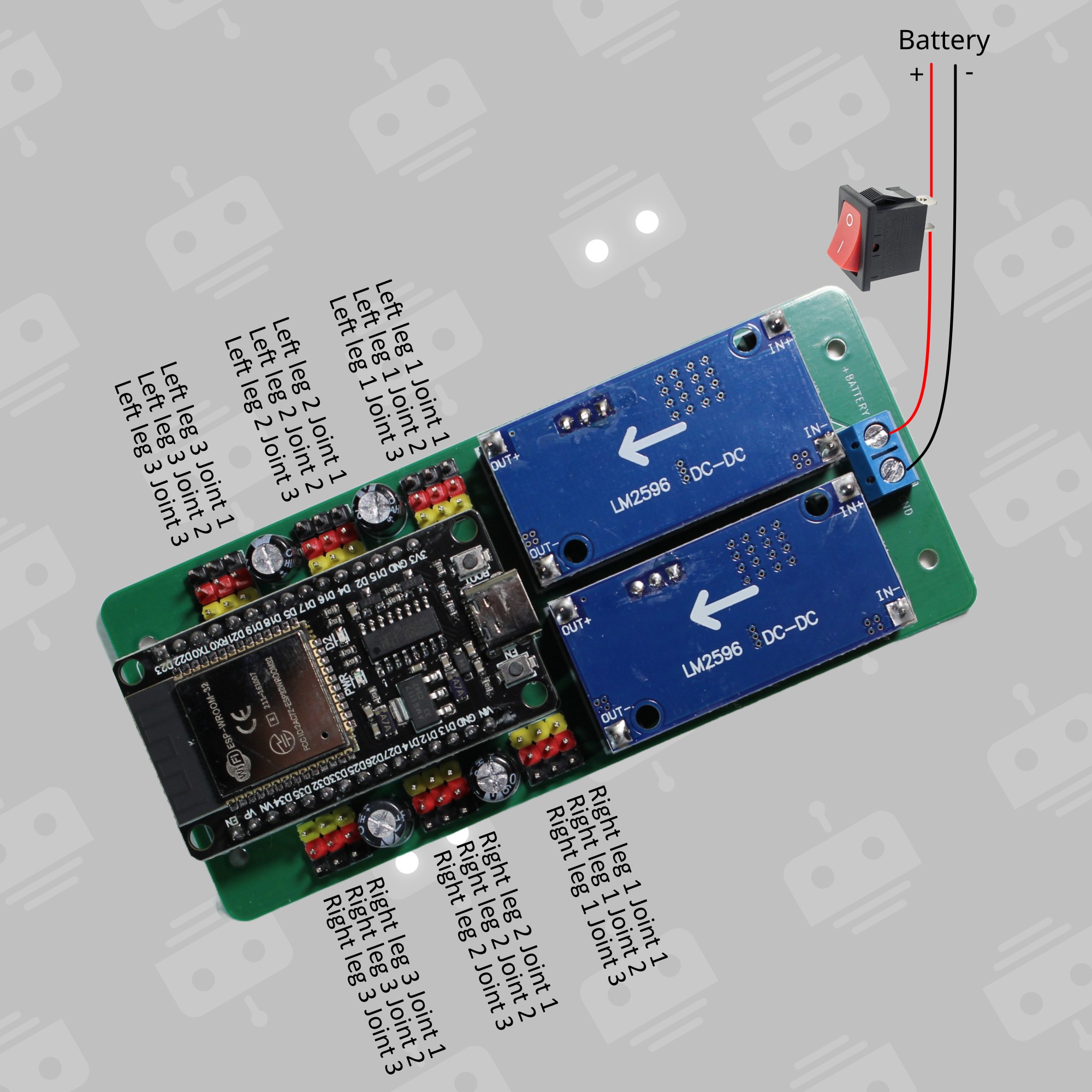
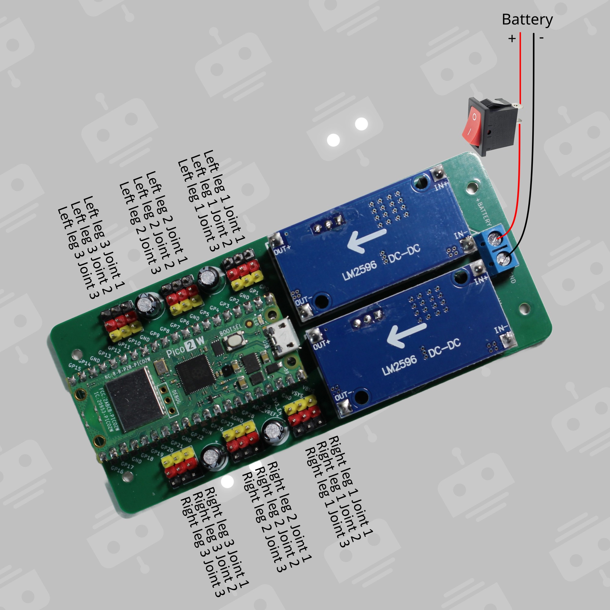
Connection Diagram
ESP32
Respberry Pi Pico W/2W
Assembly
3D-Printed Parts
Body x 1
| Filename | Thumbnail | Required # |
|---|---|---|
| body_base | <img src="./images/body_base.jpg" alt="body_base" width="400"/> | 1 |
| body_side | <img src="./images/body_side.jpg" alt="body_side" width="400"/> | 2 |
| body_front_back | <img src="./images/body_front_back.jpg" alt="body_front_back" width="400"/> | 2 |
| body_top | <img src="./images/body_top.jpg" alt="body_top" width="400"/> | 1 |
| body_top_cover | <img src="./images/body_top_cover.jpg" alt="body_servo_top" width="400"/> | 1 |
| body_battery | <img src="./images/body_battery.jpg" alt="body_battery" width="400"/> | 1 |
| body_servo_side1 | <img src="./images/body_servo_side1.jpg" alt="body_servo_side1" width="400"/> | 6 |
| body_servo_side2 | <img src="./images/body_servo_side2.jpg" alt="body_servo_side2" width="400"/> | 6 |
| body_servo_top | <img src="./images/body_servo_top.jpg" alt="body_servo_top" width="400"/> | 6 |
Use the orientations of the thumbnials to print, no support is needed.
Joint x 3 + Mirrored Joint x 3
Check the images of the fully assembled robot for the orientations of the joints and the mirrored joints
| Filename | Thumbnail | Required # | Note |
|---|---|---|---|
| joint_bottom | <img src="./images/joint_bottom.jpg" alt="joint_bottom" width="400"/> | 12 | |
| joint_cross | <img src="./images/joint_cross.jpg" alt="joint_cross" width="400"/> | 6 | |
| joint_top | <img src="./images/joint_top.jpg" alt="joint_top" width="400"/> | 12 |
Use the orientations of the thumbnials to print, no support is needed.
Leg x 6
| Filename | Thumbnail | Required # |
|---|---|---|
| leg_bottom | <img src="./images/leg_bottom.jpg" alt="leg_bottom" width="400"/> | 6 |
| leg_side | <img src="./images/leg_side.jpg" alt="leg_side" width="400"/> | 12 |
| leg_top | <img src="./images/leg_top.jpg" alt="leg_top" width="400"/> | 6 |
Use the orientations of the thumbnials to print, no support is needed.
Foot x 3 + Mirrored Foot x 3
Check the images of the fully assembled robot for the orientations of the feet and the mirrored feet
| Filename | Thumbnail | Required # | Note |
|---|---|---|---|
| foot_bottom | <img src="./images/foot_bottom.jpg" alt="foot_bottom" width="400"/> | 6 | |
| foot_top | <img src="./images/foot_top.jpg" alt="foot_top" width="400"/> | 6 | |
| foot_ground | <img src="./images/foot_ground.jpg" alt="foot_ground" width="400"/> | 6 | |
| foot_tip | <img src="./images/foot_tip.jpg" alt="foot_tip" width="400"/> | 6 |
Use the orientations of the thumbnials to print, no support is needed.
Accessory
| Filename | Thumbnail | Note |
|---|---|---|
| accessory_cable_holder | <img src="./images/accessory_cable_holder.jpg" alt="accessory_cable_holder" width="400"/> |
Use the orientations of the thumbnials to print, no support is needed.
Others
| Name | Spec | Required # |
|---|---|---|
| Screw | M2 6mm | 36 |
| Screw | M2 10mm | 198 |
| Nuts | M2 | 234 |
| Pin (304) | M4 6mm | 18 |
| Bearing | MR74-2RS (4mm ID, 7mm OD, 2.5mm Bore) | 18 |
Software

ESP32-Arduino
Source code is under ./hexapod_arduino.
hexapod_arduino.ino: Main Arduino sketchconfig.h: Configuration header. Change the configurations based on your servo connectionsmotion.h: Automatically generated motion look-up-table using `path_tool'
Android
Working in progress
PC
Working in progress
Calibration
Check the following image for the initial positions of all the leg joints while all the servos are at 90 deg.
Adjust the following two lines in in config.h to correct the installation offsets.
static int left_offset_ticks[3][3] = {{-5, 10, 0}, {-15, 5, -20}, {20, -10, 10}};
static int right_offset_ticks[3][3] = {{20, -10, 0}, {-15, 0, -5}, {-10, 0, -20}};
Files in this package
- CAD source: body_base.STL, body_battery.STL, body_side.STL, body_top.STL, body_top_cover.STL, foot_bottom.STL, foot_ground.STL, foot_tip.STL, foot_top.STL, joint_bottom.STL, joint_cross.STL, joint_top.STL (+8 more)
- Images: accessory_cable_holder.jpg, battery.jpg, battery_holder.jpg, body_front_back.jpg, body_servo_side1.jpg, body_servo_side2.jpg, foot_tip.jpg, hexapod-logo.png, joint_bottom.jpg, joint_cross.jpg, joint_top.jpg, switch.jpg
Source & license
- Original author: rookidroid
- Source repository: https://github.com/rookidroid/hexapod
- License: GPL-3.0
Imported into the CommunityCAD Archive with attribution preserved. All rights remain with the original author under the stated license.